Hydraulic Feed Controls Explanation
The hydraulic feed control units we have on offer are available in stroke lengths of 1", 2", 3",4" and 6" (See Figure 2) with a capacity of up to 1200 lbs. The hydraulic feed controls are sealed so they won’t leak hydraulic fluid unless damaged. The sealed unit prevents dirt, dust or lint that can contaminate the fluid from entering, so the internal flow aperture never silts to cause variation in plunger speed.
They are easily adjustable to your specific needs because the range of adjustment is over 300° with a very smooth, gradual rate of change. Each hydraulic feed control unit is tested at its rated capacity to check constancy, load-holding ability and adjustability.
How It Works
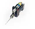
The spindle of the self-feeding drill unit is housed in a quill which moves out of and into the cylinder of the self-feeding drill unit as it advances and retracts. The hydraulic feed control unit is mounted within the stop collar, which is mounted to the end of the quill. When the spindle advances, so does the feed control unit. The hydraulic feed control unit requires a surface to act against to resist the forward motion of the self-feeding drill unit and provide a smooth, consistent feed rate.
In some cases, customers have used the surface of the workpiece for this purpose. Unfortunately, many factors can make this impractical. Blackalloy offers a feed control stop bracket which is normally quoted with every self-feeding drill unit equipped with a feed control. The feed control stop bracket is slotted and can be mounted in such a way that it provides an adjustable surface that the hydraulic feed control unit can act against.
In the case where a feed control stop bracket is utilized, the bracket is adjusted to meet the plunger of the hydraulic feed control just before the cutting tool enters the workpiece. This ensures that any excess stroke distance before the cut occurs as fast as possible while also preventing the shock of the cutting tool engaging the workpiece at full speed.
The feed control engages just before the cutting tool enters the workpiece and provides a constant rate of forward motion through the cut. In the case where the workpiece is utilized, the hydraulic feed control unit must be adjusted within the stop collar so that the plunger of the feed control contacts the workpiece just before the cutting tool.
In Figure 1 below, the self-feeding drill unit will travel at maximum stroking speed (determined by air pressure, PSI supplied to the self-feeding drill unit) through the first 1/2" of the stroke until the hydraulic feed control unit contacts the adjustable stop. When this happens, the feed control unit reduces the stroking speed to a constant adjustable rate over the remaining 1" of stroke.
Size Matters
The hydraulic feed control unit should always have a stroke length that exceeds the full depth of cut for the workpiece. If the stroke length of the feed control unit is less than the full depth of cut for the workpiece, the self-feeding drill unit will not reach the intended depth because the feed control unit has reached the limit of its travel and the self-feeding drill unit will no longer advance to the end of the stroke. Alternatively, you would have to set the feed control to engage after the cutting tool has engaged the workpiece, which reduces considerably the benefit of using a feed control unit.
In many cases you will have some excess stroke length in the self-feeding drill unit to allow clearance for loading the workpiece or to make up for variability in the workpiece, among other reasons. In these cases, it is not necessary that the stroke length of your feed control unit equal or exceed the stroke length of your self-feeding drill unit. Ideally your feed control stroke length will exceed the depth of cut required for the workpiece and no more. Else you will be purchasing stroke length you do not need and will not use.
For example, you have a 3" stroke self-feeding drill unit, and you are drilling a 1-1/4" deep hole. You would likely use a 2" stroke feed control as opposed to a 3" stroke feed control because the last 1-1/2" of stroke would never be utilized.
An exception would be a case where you have a 1-1/2" stroke self-feeding drill unit, and you are drilling a 1" hole. In all likelihood you would use a 2" stroke feed control unit to ensure that you have room for clearance at the beginning and the end of the 1" depth of cut.
Feed Rate Adjustment
1", 2", and 3" stroke length feed controls are adjusted by inserting a rod in the hole in the brass adjustment knob at the base of the unit and rotating the knob. The 4" & 6" feed controls are adjusted by turning the knurled brass adjustment knob with fingers. Turning adjustment knob full circle, will not harm the unit but do not adjust while under load. Adjustment is at its fastest setting when indicator slot is at #0 on the scale line and at its slowest setting at #30 on the scale line. The no scale area between #30 and #0 is a null area with no adjustment.
When using a hydraulic feed control unit, the feed rate is constant through the stroke length of the feed control unit. However, the feed rate is affected by load. If you adjust the cylinder to your desired feed rate while running the self-feeding drill unit at 80 PSI, then you adjust the air pressure to the self-feeding drill unit to 100 PSI, your feed rate will likely increase because the load on the feed control has increased. You will want to control and monitor these and other factors if you need to maintain a precise feed rate over time.
Positioning Considerations
Hydraulic feed control units are mounted on the self-feeding drill unit stop collar and clamped in place in a split mounting configuration. The position of the feed control unit can be adjusted within the stop collar by loosening the clamping screw and moving the feed control forward or back within the mounting hole.
The feed control unit must be clamped within the safe clamping zone to avoid crushing the cylinder and voiding the warranty. The safe clamping zone for each feed control unit is within the first 3.25", 4.25", and 5.25" for the 1", 2", & 3" feed controls respectively. For 4" and 6" feed control units, the safe clamping zone is within the reduced diameter at the front of the cylinder.
Do not twist the plunger rod within the body of the feed control unit or allow load to slide across end of plunger causing the plunger to twist during its stroke, otherwise the plunger seal and bushing life will be shortened.
Service & Maintenance Considerations
If necessary, readjust after the hydraulic feed control has reached its highest operating temperature. The maximum recommended operating temperature is 135° F. We do not recommend operation in ambient temperatures below +40° F or above +120° F.
The hydraulic feed control units are designed to operate without external lubrication. The plunger bushing and seal are permanently lubricated with a special lubricant and protected by a rod wiper. Additional lubrication of the plunger is not recommended because ordinary oil will displace the special lubricant and may shorten the long wearing life of the
unit.
Remove hydraulic feed control units from service immediately if the plunger hesitates or fails to travel all the way out on its return stroke. Keep a spare unit on hand if a breakdown would be costly. Life expectancy is millions of cycles, but any hydraulic unit will eventually wear out. When repair service is required, the unit may be returned to factory for fast, expert work at reasonable rates. The feed control units are light weight and inexpensive to ship.
Technical Specifications
| Feed Control P/N | Description | Stroke | Minimum Full Stroke Force | Return Spring Force | Plunger Return Time | 1" per Second Load | 4" per Second Load | 1000 lb. Load | 500 lb. Load | 100 lb. Load |
|---|---|---|---|---|---|---|---|---|---|---|
| K10 | Slow Speed | 1" | 5 lbs. | 4 lbs. | .378 sec. | 30 lbs. | 90 lbs. | 75 sec. | 180 sec. | 25 min. |
| K20 | Slow Speed | 2" | 5 lbs. | 4 lbs. | .730 sec. | 30 lbs. | 90 lbs. | 150 sec. | 6 min. | 50 min. |
| K30 | Slow Speed | 3" | 5 lbs. | 4 lbs. | .1.62 sec. | 30 lbs. | 90 lbs. | 225 sec. | 9 min. | 75 min. |
| K40 | Slow Speed | 4" | 5 lbs. | 4 lbs. | 1.87 sec. | 30 lbs. | 90 lbs. | 5 min. | 12 min. | 100 min. |
| K60 | Slow Speed | 6" | 8 lbs. | 7 lbs. | 2.39 sec. | 30 lbs. | 90 lbs. | 7.5 min. | 18 min. | 150 min. |
- Minimum Full Stroke Force - Minimum force that will operate plunger full stroke. (lbs.)
- Return Spring Force - Plunger return spring force. (lbs.)
- Plunger Return Time - Time required for plunger to return outward if released suddenly.
- 4" per Second Load - Load that will push plunger 4 inches per second at fastest adjustment.
- 1000 lb., 500 lb., 100 lb. Load - Time for full stroke of plunger at slowest adjustment at 1000 lb. load, 500 lb. load, and 100 lb. load.